Chapter
21d1
Fuel System
Port & Starboard Strake Sumps
The plans strake
sump blisters are there in event of an extended slightly nose down level descent
to prevent fuel starvation because if low on fuel the remaining fuel would
all be in the leading edge of the strakes.
Although we have a main center sump with greater capacity than the plans side
sumps, we retained the side sumps as a convenient way to provide a low point for
the strakes, a good place to install threaded fuel fittings and a little extra
capacity. The plans strake sumps are convex, one would assume for increased
capacity, not needing the capacity and wanting a cleaner and hopefully lower
drag profile we made them with a large concave radius. They measure about large
stewpot lid radius (5-6"?) by 12" long.
In preparation for the sump blisters an aluminum bung was cut, drilled and threaded with a tapered thread, floxed and glassed in place.
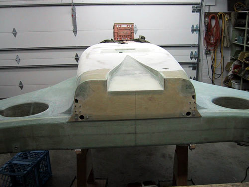
Next a foam mold form was hot wired and sanded to fit each side. In the picture below the surface of the strake and fuselage has been covered with 6 mil poly sheet, the foam mold form has been 5 minute micro'd in place and faired in with more 5 minute micro.
We have found that in the case of in-situ LoVac molding that the existing glass lay-ups can be porous to the point of disabling the process. The 6 mil poly sheet provides a seal as well as a release from the fuselage.
Next 2 layers of BID were LoVac'd in place.
Which produced this part shown below:
We carefully
marked where the sump flange mating surfaces were.
The sump areas were then coated with a mixture of MGS 335 resin mixed with
cabosil and squeegeed hard into the surface.
Excess was squeegeed off and peel ply was applied to the flange mating surfaces.
Jefco chemical resistant epoxy coating was then applied to the wetted areas of
the sumps and fuselage:
And finally the sump blisters were bonded in place with a mixture of MGS335 and cabosil, then glassed over with a single ply BID tape around the edges.