Chapter
21d
Fuel System
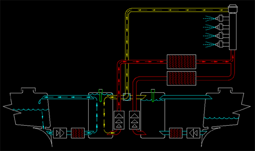
The schematic
pictured below shows the fuel delivery portion of our fuel system.
Not shown is any portion of the vent system which will be covered separately.
The system pictured here is specific to our Cozy Mk-IV which has a Mazda rotary
engine and had a center fuel sump in the area between the two main gear mounting
bulkheads, a space vacated because we do not have the plans main gear bow.
(Click Image For Larger Version)

The major
components of our fuel system in the order of flow are:
1- strake tank.
2- strake sump.
3- Facet low pressure/low flow circulation pump.
4- primary trash filter
5- feed sump.
6- EFI high pressure pump
7- fuel filter.
8- fuel rail.
9- fuel injectors
10- pressure regulator
11- return line.
12- return selector
Fuel levels are
monitored in the following manner:
1- At the time of putting fuel in the aircraft.
2- Observation of the Vance Atkinson fuel sight gauges.
3- As indicated on the BMA EFIS/One fuel gauges monitoring a pair of capacitive
fuel probes in the two strake tanks.
4- The fuel totalizer function of an EFI engine monitor under development with
Ed Anderson.
5- An optical sensor/alarm that indicates when fuel in strakes is depleted or
not getting to main sump.
6- An optical sensor/alarm that indicates when X (to be determined) amount
of altitude maintaining cruise time remains in the sump.
Fuel Management:
The system as pictured above reduces fuel management to monitoring and
determining which strake tank to take fuel from. The high pressure EFI pumps
function the same as a fuel valve in that they are either on or off, they either
flow or they do not.
Chapter
21a Your Own Strakes Kit -this is a huge time saver.
Chapter
21b Infinity Gear Installation
Chapter
21c Cozy Girrrl Strakes TM
Mod -what we did, how we did it.